doi:10.1088/1757-899X/603/3/032019
Raquel R.S.C. Silva1, Inês D.D. Campos2
1 Department of Civil Engineering and Architecture, University of Beira Interior, Calçada Fonte do Lameiro, 6200-001 Covilhã, Portugal
2 Department of Civil Engineering and Architecture, University of BeiraInterior, Calçada Fonte do Lameiro, 6200-001 Covilhã, Portugal & CIAUD,Lisbon School of Architecture. Rua Sá Nogueira, Polo Universitário, Alto da Ajuda, 1349-055, Lisboa, Portugal.
raquelcarinha@hotmail.com
1. Introduction
2. Modularity in architecture - what is it and what are its advantages
3. The modular system - concept, materiality and constructive solutions "Puzzle house"
4. Results and discussions – prototype
5. Conclusions
Abstract. This article intends to explore the concept of modularity, namely its advantages in the application to architecture projects. The world is constantly evolving, there are new needs, and architecture has to know how to respond to it. The choice of this topic rests on a very current theme - although modularity in architecture is not a recent concept, its use is becoming more and more widespread at an increasingly frenetic pace, in which time is quite valuable. Modularity is an interesting concept because of its effectiveness. There are many advantages of this working methodology - which begins at the design stage and is later reflected in its execution - and, therefore, this is an increasingly studied, developed and applied subject. When well applied, the use of modular systems proves to be quite effective. Planning is the keyword which ultimately translates into optimizing the time spent on a project and its execution, thus reducing expenses, through premeditation of problems, and the waste of raw material. The modular architecture is a very functional and appealing concept. Through a practical example in the application of the system in the rehabilitation of a street store to transform it into housing, a closed modular system – thought to be applied in rehabilitation works – is used in order to demonstrate these same advantages. This system consists of all the necessary parts for the rehabilitation of a space – a structure for the floor, the walls and the ceiling, and also includes all technical equipment – without being dependent on other constructive systems and with the advantage of being flexible and non-invasive. This article aims to raise the interest of the scientific community in this subject and to encourage the study and the application of modularity in the day-to-day practice so that in the future its use becomes the most common technique and not the exception.
1. Introduction
Understanding the concept of modularity is essential to later assimilate its advantages. The subject matter will be explored starting from theoretical concepts and using a practical example for a better understanding.
The main objective of this article is to highlight the advantages of modularity applied in architecture.
The first topic contextualizes the rest of the work and aims to define and explain what the module is, more specifically the modularity in architecture and the different types of modular systems.
Historical contextualisation is also important in order to better understand the evolution of these concepts and how the model presented was created and, therefore, a slight approach to the evolution of modularity over time will be made.
After that, the above-mentioned model will be presented: its concept, its materiality along with the constructive solutions created.
After a theoretical definition of the matter, the modular system applied to a rehabilitation project for a better understanding of the idea and its advantages will be shown.
2. Modularity in architecture - what is it and what are its advantages
“Module - Each of a set of standardized parts or independent units that can be used to build a more complex structure such as an item of furniture or a building.” [1]
The module in architecture is not a recent element. Its application has been verified over time, firstly in Greek, Roman and Japanese architecture, then extending itself up to the present day in an increasingly widespread way [2].
Since World War II, due to the need to eliminate housing problems, modular coordination has developed itself exponentially with universal standards (mostly ISO 1006-10cm, but also DIN 4172-12.5cm in Germany and 4 inches for North America and England).
Despite the existence of a system that standardizes measures at almost a global level; modular coordination remains a concept that is not always applied.
There are many advantages to applying modularity in architectural projects.
Modular coordination work often starts from a grid or a modular reticulated reference composed of dots, lines and planes (in the reticulated) that define the dimensions and proportions of spaces and its components, thus, guaranteeing conformity between elements ‘figures 1, 2, 3’.

Figure 1. Reference System [2]

Figure 2. Modular Reticulated reference [2]

Figure 3. Applied modular reticulated reference [2]
The advantages come from a crucial point in this theme: planning. In modular coordination, all elements are thought and designed to work together in a closed system in which variations are restricted, the components of this system only work together and are not compatible with any other system. It can also be opened, thus respecting a dimensional standardization in which the elements are compatible irrespective of their origin. Both methods are based on one of the systems referred above (grid or modular reticulated reference). [3]
With more or less possibility of compatibility, depending on whether the construction system is opened or closed, both aim at a "perfect" operation without wasting material.
There are numerous advantages to using this method: the little (or none) waste of material, as already mentioned; the simplification of design and of the construction process since all details are previously studied; the easiness of maintenance of the work, due to the compatibility between raw materials; the efficient control of costs, thanks to the previous planning and consequent notion of all the necessary material; the reduction of the time of construction, thus saving in terms of labour force. [4]
In a modular construction project, it is possible to have reduced prices when compared to a similar non-modular one because the waste of time and materials are minimal. In addition, it is considered a safer method since it was initially subject to further tests and studies (the materials and the conjugation between them). [2]
3. The modular system - concept, materiality and constructive solutions "Puzzle house"
Flexibility, adaptability and metamorphism are the main terms that define the concept of the developed system.
The idea was to create a system that would be adapted to pre-existences, thus respecting their original shapes. As a result, in addition to the capital gains mentioned above, we would also have the advantage of being able to apply it to places which, due to their historical, social or other value, could benefit from non-invasive intervention.
The creation of a "puzzle house" allows the flexibility, adaptability and metamorphism mentioned above, because the construction system allows changes to be made in an easy way according to the needs and desires of its inhabitants, without the need for works, and it is completely reversible just like a puzzle. By being modular, it reduces waste material, the execution time and, consequently, the associated costs.
To achieve the concept created, several parts were designed to act, as explained above, like a puzzle.
Firstly, a mesh made of metal profiles is created on the floor ‘figures 4, 5, 6’. This mesh is fixed to the existing one because it is here that the parts of the floor and also of the walls will be placed. The mesh is composed of three different pieces: two square section profiles and an omega profile, all with a 3mm thickness.

Figure 4. 1st squared section profile

Figure 5. Omega profile

Figure 6. 2nd squared section profile
It starts by applying square section metallic profiles that are placed horizontally, thus forming a quadrilateral mesh. These are 670mm in their longest length, 560mm in the shortest one and are 110mm high.
In the middle of the squares of the existing mesh, other square section metallic profiles are placed vertically. These measure 110x110mm and are 142mm high.
The omega profiles are fixed on the top of the first applied profiles and are perfectly aligned with the first ones. They have exactly the same length, so the vertices must match. The width of these profiles is 120mm.
After completing these three steps, the omega profiles that will make the roof mesh will be placed. These are placed in a mirror effect, i.e., in the same vertical alignment, but placed upside down and are attached to the floor with plugs for false ceilings. It is important to be rigorous at this stage, as it is on the omega profiles that all other parts will be set up.
The next step is the flooring application. In this case, the material chosen was OSB wood, due to its strength, easy maintenance and low cost.
Firstly, the 600x600x18mm ‘figure 7’ quadrangular panels are placed on the flaps of the omega profiles. After this, the gutters will be filled with the pieces of 600x70x47mm ‘figure 8’ and, where they intersect, with the 70x70x47mm pieces ‘figure 9’. At this stage, it is already important to keep in mind the location of the walls and leave these gutters free.
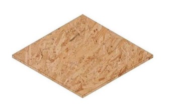
Figure 7. 600x600x18mm quadrangular panels

Figure 8. 600x70x47mm pieces

Figure 9. 70x70x47mm pieces
The next step is the ceiling application with OSB wood panels of 590x590x18mm. These will also be placed on the flaps of the omega profiles that, as they are placed in mirror with those of the pavement, will be in sight.
Both the flooring and ceiling material do not require any type of fixing system which allows easy access and maintenance of electrical and hydraulic installations.
At the end of this process, the walls are placed. These are composed of two different elements: one is a single piece and the other one is made up of eight parts ‘figures 10, 11’.

Figure 10. Eight-part element

Figure 11. Single element
The first part consists of two 60mm thick XPS insulation boards, two 22mm OSB wood panels, two 5mm thick unequal flaps and two 5mm metal sheets.
The insulation boards that must be inserted in the first place and must be aligned with the omega profile of the floor and ceiling.
The OSB wood panels are then placed. Each one should have unequal flaps on top and a metal plate at the bottom, both previously bolted and aligned with the inside of the panel. These are applied on each side of the insulation boards and should be embedded on top and placed below. Both unequal flaps and the metal sheet are slightly recessed from the outer edges of the panels, thus creating a feeling of lightness that contrasts with the rigidity of the materials chosen. In this part of the wall, a window can still be inserted where necessary. The maximum width that the window can assume is of 50cm; the height is adjustable.
The second part, which acts as a pillar, has a square section of 70mm and makes the union of the first ones, and is intercalated with these in the place where the profiles intersect. The height of these pieces depends on the location to be rehabilitated. The pillars and insulation boards have the height corresponding to the distance between the centre of the omega profiles and the pavement height. The height of the wall covering, where the height of the OSB panel is comprised, the thickness of the lower metal sheet and the thickness of the smaller flap of the angle is equivalent to the height from the quota of the floor to the lower part of the flap of the omega profiles of the ceiling.
The artificial lighting is made with tubular led bulbs of 600mm, which are applied inside the gutters, thus creating games of light able to mark and define spaces.
4. Results and discussions – prototype
The shop which was chosen to demonstrate the application of this system presented two problems at the outset: the lack of accessibility for people with reduced mobility and the small free area (about 44m2).
To solve the first problem, it was decided to change the entrance to a place where the threshold level was similar to that of the street which was the only change made to the pre-existing building. In this way, the entrance was made through the kitchen. This is not theoretically the best option but, in this case, it has proved to be the most favourable because it is the one that guarantees access to people in wheelchairs without using vertical movement mechanisms. Even so, we have tried to delineate well this area, through artificial lighting and vertical elements - the side of a closet - thus creating an abstract separation between the entrance and the boundary spaces ‘figures 12, 13, 14, 15’.

Figure 12. Floor plan
Regarding the size of the space and according to the Portuguese legislation, this was enough only for one T0, but, for comfort reasons, it was decided to delimit - without closing it - the most private place (a resting place). Thereby, a resting area connected to the room was created, but still giving it a more private character. This cannot be considered as a bedroom because it is not an independent room, but it gives the user more privacy and, consequently, more comfort than in a traditional room, where the bedroom and the living room usually merge without any separation or distinction.
The kitchen is also not an enclosed space, but it respects the free areas required for the wheelchair movement and the space for the necessary equipment: it has an L-shaped bench and is equipped with: fridge, cooker, oven, extraction fan and sink. The option of maintaining an open space was to facilitate circulation and to enjoy the natural light as much as possible.
The living room is the room with better natural lighting but, because it is also an open space, it allows the propagation of natural light through almost the entire area of the room. This area includes the living and the dining area and connects to the kitchen through a corridor where there is a storage area and also access to the sanitary installation.

Figure 13. Section AA'
The sanitary installation is contiguous to the kitchen which is beneficial in terms of hydraulic installations. It is, like the rest of the house, designed for autonomous disabled use and includes a recumbent mirror, a sink without the lower cabinet, a bench and grab bars in the shower area and next to the toilet. This room also has a cabinet designed for the installation of a washing machine, a dryer and a water heating cylinder. This is the only compartment that does not receive natural light.

Figure 14. Section BB'
In addition to these, the resting area is another one that is next to - even in a space of its own - the room that takes advantage of all its natural light.

Figure 15. Section CC'
Although in the first analysis several obstacles have been encountered, as mentioned above, these were overcome with a less traditional but at the same time functional approach to the use of space. This way, we managed to have natural light in almost all space (with the sanitary installation being the only room that does not have it) and it became a house completely adapted for wheelchairs users or with other mobility problems.
5. Conclusions
In this article, the concept of modular architecture was discussed, focusing on its advantages but also through a brief historical contextualization and a practical example.
It was concluded that modular architecture is an important concept to study and develop as it is able to respond to effective solutions of temporary or permanent nature. In general, there are numerous advantages of this concept. The system described here also has several advantages that range from the reduction of the execution and assembly time to the reduced costs of this type of construction which makes modularity a functional and appealing concept.
In order to better attest this theory and also to be able to demonstrate the functioning of the system created, a practical example was used - the transformation of an old store into a dwelling. The choice of the store was not random but rather made with the aim of showing that this can be a great system in unfavourable conditions. This way, the advantages mentioned in the article can be seen in practice.
It is believed that, in the future, modularity in architecture will be a widely used methodology, hence the need to study and demonstrate its qualities.
References
[1] Oxford University Press, Living Dictionaries, Module. [Online] 2019 [Accessed 2019] Available at: https://en.oxforddictionaries.com/definition/module
[2] V. H. B. De Sousa, “Architecture, Sustainability and Modular Coordination". Dissertation for Obtaining the Master Degree. Covilhã: UBI; pp. 5, 2011.
[3] J. P. G. Domingos. “A Modular Architecture System Offered in Wood for the Portuguese Market". Dissertation / Project to Obtain Master's Degree. Lisboa: FAUTL; pp. 7, 2013.
[4] H. A. Greven, A. S. F. Baldauf. “Introduction to Modular Construction Coordination in Brazil: An Updated Approach”. 1 ed. Porto Alegre: Collection Edition HABITARE / FINEP; pp. 35, 2007.
More research papers